 Inquiry

- Product Info
- SUMIKAEXCEL PES
- Injection molding machine and mold design
SUMIKAEXCEL PES Injection molding machine and mold design
Injection molding machine selection
SUMIKAEXCEL PES can be molded using normal in-line type injection molding machines or plunger (pre-plasticizing) type injection molding machines.
Screw, Cylinder
- Since filler-reinforced grades of SUMIKAEXCEL PES are filled with glass fibers, etc., we recommend using materials with abrasion resistance.
- The screw design should be a standard full-flight type with low shear heat generation. The use of sub-flight screws or high-mix screws is not recommended because the resin temperature may rise to 400°C or higher due to resin retention or shear heat generation.
Typical screw designs are shown below.
- L/D: screw length (L) / screw diameter (D) = approx. 20
- Compression ratio: around 2 to 2.2
- Each zone
Supply zone: Around 55%
Compression zone: around 25%
Weighing zone: Around 20% - We recommend using a screw head with a backflow prevention mechanism.
Nozzle
- The material conforms to that of the screw and cylinder.
- It is best to use an open type nozzle. Shut-off nozzles are not recommended as they have a lot of dead space and resin tends to accumulate.
- For the nozzle heater, we recommend using an independent temperature controller and a PID control method that provides good controllability.
Injection unit and control system
- Since SUMIKAEXCEL PES has a high melt viscosity, we recommend using a molding machine with a maximum injection pressure of 200 MPa or more.
- Since SUMIKAEXCEL PES has a high melt viscosity and tends to require large torque during metering, we recommend using an injection molding machine with a high-output plasticizing device.
Molding Machine Capacity
- Although it depends on the size of the product, we recommend a combination of cylinder diameter and mold clamping force that results in a weight value of 1/3 to 3/4 of the total injection capacity. Please note that if the weight value is small, there is a high possibility of various molding defects occurring due to unnecessary resin retention.
Mold Design
SUMIKAEXCEL PES has a high melt viscosity and small mold shrinkage, so please take into consideration the following points when designing the mold.
Mold Material
- For prototypes and small lot molding, carbon steel for machine structures (S55C) can be used, but if there are sliding parts, we recommend hardening.
- When mass production or high dimensional accuracy is required, we recommend using tougher chrome molybdenum steel (SCM435, SCM440) or alloy tool steel (SKD11, SKD61).
- If you use materials other than those listed above, please consider carefully in advance whether there will be any problems. (We do not recommend using Cu-based alloys as mold materials.)
Sprue
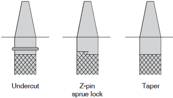
- We recommend that the length be as short as possible and the taper be large (up to 5°).
- To improve sprue removal, it is recommended to provide a sprue lock as shown in the figure.
Figure 4-3-1 Sprue shape
Runner
- Make it as thick and short as possible, and take fluidity into account when making your decision.
- A circular or trapezoidal cross-sectional shape is recommended.
- It is important to balance the gates.
Figure 4-3-2 Runner shape
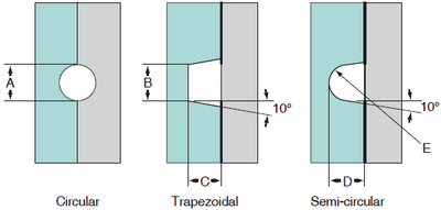
Example of runner cross-sectional dimensions (mm)
| A | B | C | D | E |
| >4 | >3 | >3 | >4 | D/2 |
Gate System
Side gate
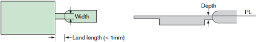
- Rectangular gates are more efficient when the land length is short and the depth is deep. The gate depth should be approximately 0.7 times the molded product thickness, and we recommend a land length of 1 mm or less.
Figure 4-3-3 Side gate shape
Pinpoint/Submarine Gate
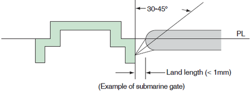
- We recommend a gate diameter of 0.8 to 1.2 mm and a land length of 1 mm or less. If the flow distance is long, we recommend a multi-point gate rather than a larger gate diameter.
Figure 4-3-4 Pinpoint/Submarine Gate Shape
Film Gate
- The gate thickness should preferably be 0.5 times the molded product thickness, and the land length should preferably be 1 mm or less.
Figure 4-3-5 Film gate shape

Pull Taper
- Since SUMIKAEXCEL PES has a small mold shrinkage rate, even shallow cuts require a draft taper of 1° (1/60) to 2° (1/30). For deeper cuts, we recommend a larger draft taper.
- Thin-walled molded products are prone to overfilling, so we recommend using a larger draft taper.
- For glass fiber reinforced grades, we also recommend a larger draft angle.
- If a sufficient taper cannot be obtained due to the shape of the product, a slide core or ejection method will need to be devised.
Air vent (gas release)
- For SUMIKAEXCEL PES, an air vent of about 1/100 to 5/100 mm is suitable. Because SUMIKAEXCEL PES has a high melt viscosity, burrs are unlikely to occur even if a 5/100 mm air vent is installed.
- Thin-walled molded products require the installation of air vents.