 Inquiry

- Product Info
- SUMIKASUPER LCP
- Injection Molding Machine and Mold Design for SUMIKASUPER LCP
Injection Molding Machine and Mold Design for SUMIKASUPER LCP
Injection molding machine selection
SUMIKASUPER LCP can be molded using a normal in-line type injection molding machine or a plunger (pre-plasticizing) type injection molding machine. However, the E5000 series requires a high-temperature specification (450°C specification) because the molding temperature is a maximum of 420°C.
Screw, Cylinder
- Many of the SUMIKASUPER LCP grades are glass fiber filled, so abrasion resistant materials are recommended.
- The screw design should be a standard full-flight type. Screws with sub-flight or high mixing capacity are not suitable as they will require longer metering times.
- The typical screw designs are as follows:
L/D (screw length (L) / screw diameter (D)): Approximately 18 to 22
Compression ratio: around 2 to 2.2
Each zone ratio:
Supply zone: Around 55%
Compression zone: around 25%
Weighing zone: Around 20% - We recommend that the screw head be equipped with a backflow prevention mechanism.
- Since the flow characteristics of SUMIKASUPER LCP are sensitive to temperature, a PID control method with good cylinder temperature controllability is required.
- The screw and cylinder require proper maintenance. Regularly monitor the check ring and the clearance between the cylinder and screw to ensure they meet the molding machine manufacturer's specifications.
Nozzle
- The nozzle material conforms to the screw and cylinder material.
- We recommend using an open type nozzle. Avoid using shut-off nozzles as they have a lot of dead space and resin tends to accumulate.
- The nozzle heater uses an independent temperature controller and requires a PID control method with good controllability.
- If each molding machine manufacturer has a nozzle specifically for LCP, using the nozzle will enable you to prevent runny nose and stringiness without lowering the nozzle temperature too much.
- The use of an extension nozzle is not recommended. If you do use one, be sure to use one that ensures uniform temperature distribution.
Injection unit and its control system
- General open-loop control type and closed-loop control type molding machines can be used.
- SUMIKASUPER LCP has a high shear rate dependency of melt viscosity and the resin hardens quickly, so when molding thin-walled products, we recommend using a molding machine with excellent injection speed startup responsiveness.
Molding Machine Capacity
- We recommend selecting a molding machine with a weighing value of 1/3 to 3/4 of the total injection capacity. If the weighing value is too small, resin will be more likely to accumulate, increasing the possibility of various molding defects. In particular, when producing ultra-small molded products or prototypes with a small number of parts, the weighing value may become small and be affected by retention, so please select an appropriate molding machine capacity and screw diameter.
- When shortening the metering time to shorten the cycle, make sure the metered value is 1/2 or less of the total injection volume.
Resin temperature control
In general, the mechanical properties, melt viscosity, and other physical properties of LCP are highly temperature dependent, and improper temperature management may result in insufficient properties being obtained. Injection molding machines are designed so that the resin temperature inside the cylinder is relatively close to the set temperature at the molding temperature of general-purpose resins (up to 300°C), but in the molding temperature range of SUMIKASUPER LCP (320-400°C), there may be cases where there is a discrepancy between the set temperature and the resin temperature.
To maximize the performance of SUMIKASUPER LCP, it is necessary to understand the resin temperature inside the cylinder and control it to the optimum temperature for each grade.
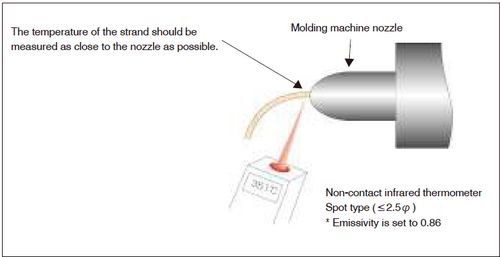
The resin temperature mentioned above can be easily measured by using a spot-type non-contact infrared thermometer that can measure the temperature of a very small area (less than the diameter of the strand).
Figure 4-3-1 SUMIKASUPER LCP resin temperature control method
High Speed Injection Molding Technology
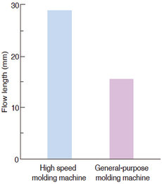
SUMIKASUPER LCP has a low melt viscosity during molding and a fast solidification speed, which means that flash is unlikely to occur. However, when molding ultra-thin walled products (<0.2mm), the resin may solidify in the thin walled area and sufficient flow length may not be obtained. In such cases, it is effective to use an electric injection molding machine with excellent start-up characteristics during injection or a hydraulic injection molding machine with an accumulator.
Figure 4-3-2 Maximum flow length without Flash Generation
Hydraulic injection molding machine:
UH-1000 [Nissei Plastic Industrial Co., Ltd.]
Electric injection molding machine:
SE/SV Series [Sumitomo Heavy Industries, Ltd.]
Electric injection molding machine:
FANUC ROBOSHOT α-Si series [FANUC LTD.]
Electric injection molding machine:
LP/TR Series [Sodick Co., Ltd.]
Figure 4-3-3 Comparison of Injection Response Characteristics
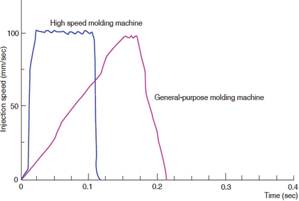
(Compared to general-purpose molding machines, the high-speed molding machine has a faster initial rise in injection speed, indicating that molding is performed at the specified injection speed.)
| Flow length measurement mold: | Use the one in Figure 4-3-5 |
| Molding temperature: | 360℃ Grade used: E6008 Injection speed: 600mm/sec VP switching pressure 60MPa |
| General purpose molding machines: | Nissei Plastic Industry PS-40E5 ASE Injection speed 90% Injection pressure 90MPa |
Mold Design
When SUMIKASUPER LCP is injection molded (by applying shear), the molecules easily orient in the flow direction, resulting in molded products with excellent fluidity, high strength, and high elasticity, but on the other hand, anisotropy occurs. When designing the mold, it is necessary to take into consideration the flow pattern and anisotropy inside the cavity.
Mold Material
- For prototypes and small lot molding, carbon steel for machine structures (S55C) can be used, but if there are sliding parts, we recommend hardening.
- Many of the standard grades of SUMIKASUPER LCP are filled with glass fiber, so for dies and mass-produced molds that require high dimensional accuracy, we recommend using a steel material with a hardness of HRC55 to 62 equivalent to SKD11 (HPM31, PD613, RIGOR, etc.) or higher.
- SUMIKASUPER LCP generates almost no corrosive gases, so it will not corrode molds and general mold materials can be used. However, if you use a material with a mold hardness of less than HRC55, please consider in advance whether there will be any problems.
Sprue
- The appropriate sprue draft angle is 1° to 2° (one side).
- To remove cold slug, we recommend providing a cold slug reservoir at the sprue end (4 to 5 mmφ x 5 mm or more).
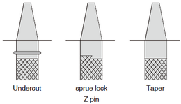
- To improve sprue removal, we recommend providing a sprue lock.
Figure 4-3-4 Sprue diagram
Runner
- Runners with typical circular, semicircular, trapezoidal, and semi-trapezoidal cross-sectional shapes can be used, but circular or semi-trapezoidal shapes are recommended due to pressure loss and workability. SUMIKASUPER LCP has excellent fluidity, so the runner diameter can be made thin. The standard runner diameter is 2 to 5 mmφ, and the recommended runner diameter is 2/3 to 1/2 that of PPS and PBT (minimum 1.5 mmφ).
- For multi-cavity molding, we recommend balancing the runners so that each cavity is filled with resin at the same time. We also recommend providing a cold slug reservoir at the end of the runner.
Figure 4-3-5 Thin-wall flow length measurement mold (unit: mm)
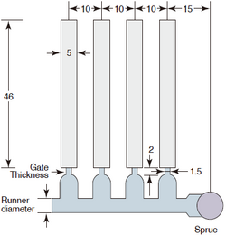
Product thickness: 0.3mm
Flow length is 4 cavities average.
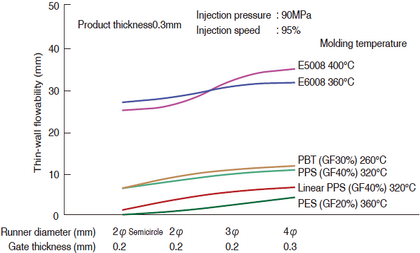
Figure 4-3-6 Thin-wall flow length
Gate
Since SUMIKASUPER LCP has lower weld strength than other engineering plastics, it is necessary to limit the number of gates to one and carefully consider the gate position to prevent welds as much as possible.
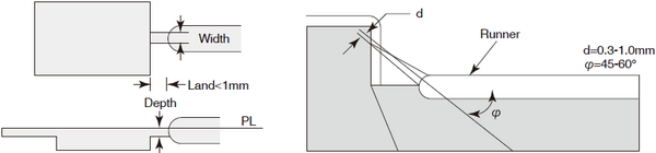
- Side gate
The appropriate land length is 1mm or less, and the appropriate width is 5mm or less. The land depth is approximately 0.7 x the molded product thickness, with a minimum of 0.2mm being appropriate. - Pinpoint Gate
A gate diameter of 0.3 to 1.5 mm and a land length of 1 mm or less are appropriate.
If the gate diameter is made too large, it may cause stringing or gate curling. - Submarine (tunnel) gate
A gate diameter of 0.3 to 1.0 mm is appropriate. - Film gates and ring gates are also possible, but are less common for LCP.
Figure 4-3-7 Gate diagram
Pull Taper
- For shallow molded products, 0.5° (1/90) to 1° (1/60) is appropriate, and for deep molded products, 1° (1/60) to 2° (1/30) is appropriate.
- The good release (MR) grade has half the release resistance compared to the general grade, but for molded products with a large depth, the ejection taper must be made larger.
Air vent (gas release)
- Since SUMIKASUPER LCP molding is often performed under high speed injection conditions, please install an air vent to efficiently remove air from the product area.
- For thin-walled products or products with welds at the flow end, be sure to install an air vent to prevent short shots and insufficient weld strength.
- SUMIKASUPER LCP has low melt viscosity and excellent fluidity, but because it solidifies very quickly, flash is unlikely to occur even when air vents are installed.
- The appropriate depth for the air vent is 0.005 to 0.02 mm.
Hot Runner Applications
Generally, resins tend to accumulate in the dead space of the molding machine during long-term continuous molding, and the resin may deteriorate or become discolored. With LCP, which has an extremely low melt viscosity, it is thought that this type of retention in the dead space is likely to occur. For this reason, it is recommended to use a hot runner that takes this into consideration, and it is particularly important to take great care to prevent the occurrence of black spots and cold slugs due to resin retention.
Key points for applying hot runners to SUMIKASUPER LCP
When selecting a SUMIKASUPER LCP hot runner, please pay attention to the following points.
-
Capable of high temperature heating and uniform temperature distribution within the system.
A heater-integrated type is preferable. Do not raise the manifold and nozzle temperatures excessively.
The temperature of the part in contact with the mold (gate part) can be maintained at a high temperature.Table 4-3-1 Hot runner temperature specifications
Hot runner temperature specifications (MAX) E6000HF Series ~370℃ E6000 Series ~380℃ E4000 Series ~400℃ E5000 Series ~420℃ - The structure is such that dead space is unlikely to occur in the flow path.
(Be careful of black spots caused by water retention.)
Regarding the heating method, an external heating method is more suitable than an internal heating method, and a narrower flow path is better. - The structure is designed to prevent cold slag from getting mixed in.
(Care must be taken to avoid cold slug contamination of the product)
In the case of an open gate, it is advisable to consider installing a sub-runner (sprueless molding).
Application of hot runner to SUMIKASUPER LCP
Table 4-3-2 Application of hot runner to SUMIKASUPER LCP
| Runner Section | Gate seal | SUMIKASUPER Application to LCP |
remarks | ||||||
|---|---|---|---|---|---|---|---|---|---|
| internal heating |
external heating |
Oh Pun |
valve gate |
Heat seal | Perfect Hot Runner |
Sprueless Molding |
|||
| Juoh Co., Ltd. 614 System |
- | ✓ | - | - | ✓ | - | ○ | φ4 Electromagnetic induction heating |
|
| Myojo Metals Co., Ltd. Mini Runner |
- | ✓ | ✓ | - | - | × | ○ | *1 | |
| Century Industries Co., Ltd. Spear System |
Type B (conventional) | ✓ | - | - | - | ✓ | × | × | |
| EH type | - | ✓ | - | - | ✓ | × | ○ | *2 | |
| Mold Master Co., Ltd. Master Shot |
- | ✓ | ✓ | ✓ | - | × | ○ | ||
| Saito Machinery Co., Ltd. Plagate System |
- | ✓ | - | - | ✓ | × | - | ||
○: Applicable to SUMIKASUPER LCP.
×: Not applicable to SUMIKASUPER LCP.
| *1: | When using a multi-point gate and mini-runner extension nozzles, it is preferable to control the temperature of each extension nozzle individually. Also, for the E5000 series, which has a high molding temperature, it is preferable to control the temperature of each nozzle individually. |
| *2: | The tip is internally heated. |